
As the spray stream is manipulated over the part, overlapping occurs. After several passes, a typical coating microstructure may include some porosity, unmelted or resolidified particles, fine particles, debris, and oxides. Depending on hood and dust collector design, masking and tooling, and airflow around the part, fumes from vaporized feedstock may be trapped in the layers between passes.
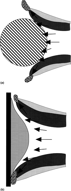
There are two basic concepts related to part geometry. First, when spraying small target areas, inclusion of unmelts and other debris is reduced. The shaft diameter is smaller than the spray pattern diameter; consequently, one-half of the spray stream actually misses the substrate.
In larger target areas, the entire spray pattern is captured on the substrate when traversed across and/or up and down. To state the obvious, process efficiency is poor when coating small parts, because of the low target efficiency.
The second concept is that small, round parts do not behave as flat surfaces, due to the angle of impingement. As a rule of thumb, curved surfaces begin to approximate flat surfaces at radii above 40 mm (1.5 in.).
Image – How part geometry affects coating deposition. (a) A small target has peripheral debris missing the substrate, while (b) a larger target collects all the peripheral debris and oxides.
This information is from ASM Handbooks Online, Vol. 5A: Thermal Spray Technology, Coating Structures, Properties, and Materials. To find this information (subscription required), click on the link below and scroll down to Figure 15.
https://dl.asminternational.org/handbooks/book/12/chapter/134972/Introduction-to-Coating-Design-and-Processing